|
|
Global remote control of mains sockets using Raspberry Pi
|

August 2012 (Last updated 31 October 2013)
This short
video clip demonstrates turning on and off a desk lamp from over 100 miles away.
Visual feedback in the video is achieved by the use of a CCTV IP camera at the
same site as the desk lamp. If the video is not playing in your browser you can
try this link instead.
Overview
and Objective
The objective was
to see how easy it would be to use a Raspberry Pi to allow remote access to
turn power sockets on or off, in some building somewhere else on the planet.
One limitation was that I needed a method of switching mains which was safe and
left no chance for exposed lethal voltages. This was nothing to do with
protecting electronics, but to do with protecting against injury. One obvious
candidate was to somehow harness a remote control power switching unit - which
are reasonably cheap and available. I got this
from Maplin and decided to work with it.
Method
of Switching
The internals of the
remote control handset is a matrix of switches which feed into an encoder. The
encoder outputs a different pulse train (on its DOut
pin) depending on which button is pressed. This feeds into a 433Mhz RF
transmitter which sends the pulse train out towards the RF receivers in the
mains sockets.
So the idea was to
replace the remote control handset with the Raspberry Pi and get that to turn
the sockets on and off. There seem to be two methods of achieving this. One was
to replace each physical switch on the remote control with a GPIO output,
another was to fake the output of the encoder and feed that into the RF
transmitter. I didn’t like the former, simply because it required many GPIO
pins to be used. There were eight switches in the handset, and each of these
was double pole, as the encoder/RF needed to be turned on at the same time that
the pulse was generated. I am sure this matrix would have condensed down by
multiplexing the outputs, but this did not seem as elegant as faking the
encoder and using one pin for the signal, and possibly one pin to turn the RF
on. Also, if the truth be told, the latter option just seemed like more fun
anyway.
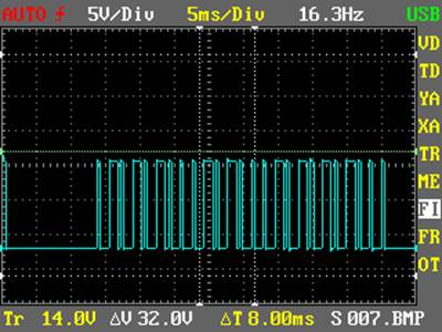
Determining
the pulse train patterns for each switch
Images of each
waveform were captured and analysed, for example :
The pulse width was
measured at 428us
There are two main
sub-patterns in use, each is 8 pulses (3.424ms long)
Button 1 On Button 3 Off
|
0 = |
(high low low low high low low
low) |
|
1 = |
(high low low low high high high low) |
|
S = |
There is a third
pattern, used as a sync marker at the end of a message
(1 high pulse, 31
low) |


Message
Format
The message
contained within the each pulse train consists of the following four parts:
|
Socket group |
1-4 |
four
* 8 bit patterns, see below |
|
Socket number |
1-4 |
four
* 8 bit patterns, see below |
|
Command |
1
for on, 0 for off |
four
* 8 bit patterns, see below |
|
Sync |
|
See
“S” above |
Socket Group,
Socket Number
Socket group and socket
number are made up of 4 8 bit patterns each, filled with 1's with a 0 to mark
the number being represented, as follows
0111 = group or
socket 1
1011 = group or
socket 2
1101 = group or
socket 3
1110 = group or
socket 4
So group 3, socket
1 would be
1101 1000
Group 4, socket 2
would be
1110 0100
Command
The command is also
made up of 4 8 bit patterns, the first three are 1. The last one is 1 for on,
and 0 for off.
Examples.
To turn Group4
socket 1 off we would send
1110 0111 1110 S
To turn Group3
socket 3 on we would send
1101 1101 1111 S
Simulating
the Remote Control Handset
These signals were
then implemented in C code (sckctrl.c) such that
command line parameters could be passed to the executable specifying a group/button/state.
Note that if you hold a button down on the remote control handset is repeats
the pulse train until you stop. If there are other 433Mhz
transmitters nearby this may be important to ensure the signal reaches the
receiver cleanly, so a parameter was included the number of repetitions of the
pulse train transmission, to be set. The command line parameters were of the
form :
<group> <socket> <state> <number
of repetitions>
Mike McCauley’s GPIO library, C
library for Broadcom BCM 2835 (thank you Mike) was used to transmit
the chosen pulse trains to GPIO pin GPIO11. The waveforms were checked with a
scope. However the voltage was obviously 0/3.3v. In order to generate maximum
RF power, a 0/12v signal would be needed.
An update to the C
code was needed after versions after 1.9 of the bcm2835 library to ensure a
fundamental pulse width of around 428 us because the the
way that the timing routines had been implemented changed in this version of
the library. The timing in the code assumes that the Raspberry Pi has not been
overclocked.
Adding
RF
|
To
implement a faked remote control for proof of concept, I added one of these 434MHz RF
transmitters to a veroboard circuit. The pulse
train was stepped up to 12v via a transistor. It was now possible to turn any
of the five sockets I had, on or off by running the code from Putty. |
|
Schematic/Circuit
Diagram
|
|
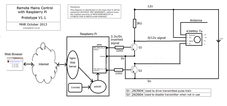
Stepping signal up to 12v.
Stepping the pulse
train up to 12v from 3.3v was achieved using an npn transistor (Q1), with a collector resistor of
1KR, and a base resistor of 22KR to ensure that with a transistor hfe of 100, and a base/emitter voltage of 0.85v, at least
8ma was available via the collector. The one problem here of course was that
this inverted the signal. A simple modification was made to the C code so that
it produced an inverted signal at the GPIO pin, giving a correct polarity of
0/12v at the collector once it was inverted again by the transistor.
The code and the
circuit also ensure that the RF is only enabled when we want to transmit a
pulse train. This is done from the GPIO
via transistor Q2. Again the base resistor value of 22KR ensures that at least
8ma (11ma in fact) can flow through the transmitter to ground.
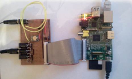
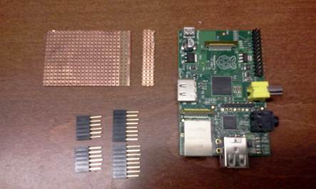
Constructing
a shield
Having achieved a proof
of concept, what I wanted to do was to mount the transmitter inside the
Raspberry Pi box rather than have it on a trailing lead. At the time of writing (August 2012) there
was one prototyping
shield I was aware of for the for the Raspberry Pi, but this seems geared
up to RF comms and does not have the density of holes
I would like. The obvious option was to
make one from some veroboard and headers I had lying
around.
I then constructed
the transmitter and added a 6 pin socket read to receive the on/off feedback
signals to the software – which is a bit more compact than adding 4* 5v sockets
to the board, as was done in the original prototype.
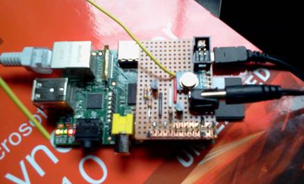
This worked fine,
but needed a very slight trim to the power socket to make it a snug fit inside
the cardboard Pi case (punnet).
By this time I had
realised that feeding back a DC voltage to indicate the state of each socket
was really not that practical. What was needed was a full duplex comms system where the receiver could transmit back when it
had turned the socket on or off.
This made me
consider a more general platform architecture for using for telemetry and
control hosted by a Raspberry Pi. This would allow not just digital outputs to
turn sockets on or off and other things, but analogue outputs and analogue
inputs to be fed between the hosting raspberry pi and multiple intelligent
remote terminal units. But that would be for another project.
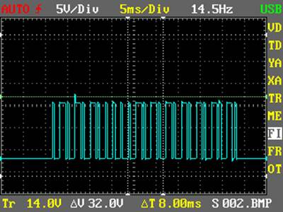
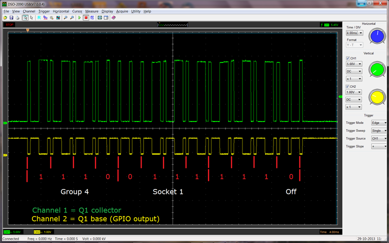
Output
from Circuit
The shield circuit
was scoped to check pulse widths and voltage levels. The inverted GPIO output
from the (channel 2 in yellow) and the 12v stepped up (channel 1, in green)
scoped signals are shown here for a command driving group 4, socket 1,
off. Note that the signals are inversely
related.
Driving
from a web page
|
The real
usefulness of being able to turn sockets on and off would be to be able to
drive it remotely from anywhere globally where there was an internet
connection. One would not normally use
a multitasking operating system to generate a 2Khz waveform, so there has to
be some reason for this compromise. nginx is a web server which is very quick to
install and configure on the Raspberry Pi. It was then fairly straight
forward to add some html buttons representing on and off for each socket to a
web page, and then using some basic JavaScript and PHP, invoke the program
written above from the chosen button, passing in the appropriate parameters. A quick tweak to the port forwarding on my
internet router for port 80, and it was now possible to control the sockets
from hundreds of miles away. |
|

Socket
State Feedback
I thought it was
important to be able to display on the web page, whether each socket was turned
on or off. It would be easy to contrive things within the web page software to
show the socket state based on whether On or Off was
the last button pressed. However this seemed pointless,
and a proper end to end solution was sought. This was achieved by allocating a
text file for each socket, which would either hold a 1 (on) or a 0 (off). The
webpage would read these files and show a green led for a 1 and a grey one for
a zero. Next, a cheap 5v phone charger was plugged into each socket's power
distribution block and this was connected to a GPIO input via a resistor
divider (330R/680R) to drop it down to 3.3v. Each of the four socket feedback
GPIO inputs was set with its internal resistor set to pull down because when
the socket was turned off, we get 0v, and we want a 0 input for that case, not
to float to a 1.
The final link in
the chain was another C program which was added to /etc/rc.local so that it automatically started on reboot of the
raspberry pi. This program simply polled the four inputs, if any state changed, the appropriate text file had its state changed,
which would be picked up by the webpage the next time it polled the file, and
would then change its HTML LED image accordingly.
Use
of Cron
Although the Web
user interface has its uses, I have started to make use of cron
on the Raspberry Pi, to automate turning sockets (mainly switching lights) on
and off. The crontab
I am using looks a bit like this :
#
# m
h dom mon dow command
# living
room 4:4
45 18 * * * sudo /webroot/sckctrl 4 4 1 10
0 2 *
* * sudo /webroot/sckctrl 4 4 0 10
# dining
room 4:3
30 22 * * * sudo /webroot/sckctrl 4 3 1 10
45 23 * * * sudo /webroot/sckctrl 4 3 0 10
30 1 * * * sudo
/webroot/sckctrl 4 3 1 10
30 2 * * * sudo
/webroot/sckctrl 4 3 0 10
# Study 4:2
30 21 * * * sudo /webroot/sckctrl 4 2 1 10
00 22 * * * sudo /webroot/sckctrl 4 2 0 10
30 3 * * * sudo
/webroot/sckctrl 4 2 1 10
35 3 * * * sudo
/webroot/sckctrl 4 2 0 10
# kitchen
4:1
20 22 * * * sudo /webroot/sckctrl 4 1 1 10
30 22 * * * sudo /webroot/sckctrl 4 1 0 10
38 1 * * * sudo
/webroot/sckctrl 4 1 1 10
39 1 * * * sudo
/webctrl/sckctrl 4 1 0 10
# Bedroom2 3:3
00 21 * * * sudo /webroot/sckctrl 3 3 1 10
35 0 * * * sudo
/webroot/sckctrl 3 3 0 10
11 4 * * * sudo
/webroot/sckctrl 3 3 1 10
31 4 * * * sudo
/webroot/sckctrl 3 3 0 10
This is obviously
just getting cron to run the sckctrl
program with the necessary group/socket/state and repetitions (10 seems good)
at the chosen time (mm hh).
This is very easy
to change (using crontab –e) and it should be possible to automate
changing crontabs based on day of week or month of
year. It should also be reasonably
straight forward to modify these settings from a web page if necessary.
Other
Issues
a) RF
Regulations
Within the UK, the Ofcom
UK Interface Requirements 2030 document suggests that there is a 10% duty
cycle (per hour) for 433.05- 434.79 MHz devices. The
original prototype had the
transmitter turned on permanently (modulating regardless of whether a signal
was being sent over it), and whilst I doubt this ruling has
much significance in my
case, it seemed sensible to only turn it on when transmitting. Hence the reason for Q2 in the circuit.
b) Phone
Charger Capacitance
Although everything seemed to work as
expected, one wrinkle was that due to the internal capacitor smoothing of the
phone charger, it did not drop to 0v for
around 2s after the
socket was turned off. This was duly reflected in a delay changing the HTML
image from green to grey when turning off the image. This was
improved by adding a 50R
resistor (calculated to 52R) of suitable power rating across the output of each
supply, but there is probably more work required in this
area to improve the way
power state is fed back. OK for a proof of concept though.
c)
Work in Progress
Note that this page is still being added
to, and in the meantime please direct any corrections or requests for
additional information (e.g. web server configuration details, source code
etc.) to the email address at the top of the page, and I will add it as soon as
I can.
Warning: This project is a prototype, built
for fun and proof of concept.
Downloads are therefore made available in
the hope that they will be useful, but without any warranty; without even the
implied warranty of merchantability or fitness for a particular purpose. All
source code is made available under GNU General Public License.
Encoder Waveforms scoped from
Remote control
sckctrl.c - C Source code to drive transmitter circuit
from Raspberry Pi