|
|
Supervisory Control And Monitoring Platform (SCAMP)
September 2013 |


Contents
Part Three: A SCAMP PID
Application
Monitoring the Process
Variable
PID Data Settings
for 50 degrees C Quality Street tin
Background
This project originally grew out of a design shortcoming in another, which used a Raspberry Pi to mimic a remote control, allowing a user to turn power sockets on or off from a web browser. It all worked really nicely. However because the user was not able to witness the sockets actually turning on or off (they could be hundreds of miles away when using the web page), they got no feedback indicating whether the operation had worked or not. Ideally the user interface would have shown the state of the socket before and after buttons were pressed.
The idea therefore in this project was to set up a duplex dialogue so
that a master device could send commands to not only set states on remote
device outputs, but also send commands to read
them back (or have them sent back),
and, in addition read back inputs to the remote device from the outside world
too. It also seemed that the ability to
control and monitor one or more remote devices (each with its own I/O
capabilities), from a web page would provide a nice general platform for lots
of hobby projects. Whether that be home
automation, a PID controlled fridge brewery, a weather station, a remote
controlled robot, garden watering management – all of these types of projects
could be implemented on top of this kind of architecture – with much of the
infrastructure all taken care of.
Terminology
As this architecture is in the
spirit of SCADA, and because this project is aiming to provide a platform on
which to build lots of other projects, the term Supervisory Control And
Monitoring Platform or SCAMP was
coined for it.
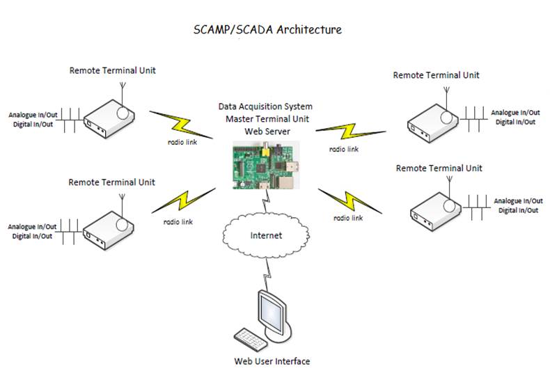
I have adopted the SCADA terms
RTU (Remote Terminal Unit) to describe the remote devices, and MTU (Master
Terminal Unit) which would the device which the user would interact with via
its web server, and which in turn would communicate with the RTUs.
Outline Requirements
1.
SCAMP
will be a general use SCADA system for use as a hobby project platform.
2.
Each
RTU should be addressable by the MTU, and its address should be determined by a
hardware jumper on the RTU so that it is not code dependent.
3.
Each
RTU should offer a number of inputs and outputs (termed “channels”), but where
possible, the design should not be dependent on any specific RTU
microcontroller.
4.
For the
initial design a fixed set channels should be defined. This IO profile should
be changeable in the longer term if necessary.
5.
Each
channel should have integer and float EEPROM associated with it.
6.
Each
RTU should have application integer and float RAM and EEPROM available.
7.
The MTU
should support a web user interface and be accessible after authentication,
over the internet as well as locally.
8.
All I/O
channels should be able to be monitored the user interface via the MTU. Output channels should be writable from the
user interface via the MTU.
9.
All
channel EEPROM and application RAM and EEPROM should be able to be read from
and written to from the user interface via the MTU.
10.
Unless
a specific application requires otherwise, RTUs should be autonomous and
capable of carrying out their application independently of the MTU.
11.
The physical
radio communications interface on both MTU and RTUs should allow the capability
for radio devices to be changed if necessary so that range can be increased with
minimum (or zero) disruption to the application code base. The range of the initial MTU to RTU link
should be up to 200 meters.
12.
The
RTUs and the MTU may need to operate on the same radio frequency, so will need
to cooperate to avoid transmitting over each other.
Part
one: Design
Channels
The I/O pins on the RTU are referred to as channels; each channel is configured as a specific type (digital input, digital output, analogue input and analogue output). In order to be truly application independent it should be possible to configure the I/O type on each channel, but this is not being considered for the initial design which will have a fixed I/O profile, as follows:
|
Channel |
Type |
|
1 |
Analogue output |
|
2 |
Analogue output |
|
3 |
Digital output |
|
4 |
Digital output |
|
5 |
Analogue Input |
|
6 |
Analogue Input |
|
7 |
Digital Input |
|
8 |
Digital Input |
|
9 |
Digital Input |
RTU Addressing
Each RTU has a distinct address which is expected to be configured using physical pins on their circuit board. The master device is always device “0” and the message space currently envisages up to 9 (“1”-“9”) RTUs under the control of an MTU. For broadcast operations the address “*” is used.
RTU Memory
Map
RAM and EEPROM is available,
mapped as application (per RTU) and channel (specific to a given channel on
each RTU)
SCAMP Application Data
There are 9 integers and 9 floats of application RAM, and 9 integers and 9 floats of EEPROM available to each RTU which can be accessed by both the RTU and the MTU.
1) Application RAM Float 0 to float 9, Integer 0 to Integer 9
|
|
0 |
1 |
2 |
3 |
4 |
5 |
6 |
7 |
8 |
9 |
|
Float (f) |
|
|
|
|
|
|
|
|
|
|
|
Integer (i) |
|
|
|
|
|
|
|
|
|
|
2) Application EEPROM Float 0 to float 9, Integer 0 to Integer 9
|
|
0 |
1 |
2 |
3 |
4 |
5 |
6 |
7 |
8 |
9 |
|
Float (f) |
|
|
|
|
|
|
|
|
|
|
|
Integer (i) |
|
|
|
|
|
|
|
|
|
|
SCAMP Channel Data
Each channel has one value holding the state of the I/O. These can all be read by the MTU/RTU and outputs may be written to. In addition each RTU channel has 9 integers and 9 floats of EEPROM which can be accessed by the RTU and the MTU.
1) Channel RAM (values on I/O pins) Channel 1-Channel 9. Data type dependent on Channel Type
|
Channel |
I/O
value |
|
|
0 |
|
channel
“0” represents commands which operate on all channels. See example below |
|
1 |
|
|
|
2 |
|
|
|
3 |
|
|
|
4 |
|
|
|
5 |
|
|
|
6 |
|
|
|
7 |
|
|
|
8 |
|
|
|
9 |
|
2) Channel EEPROM For each Channel 1-9 , Float 0 to float 9, Integer 0 to Integer 9
|
Channel |
|
0 |
1 |
2 |
3 |
4 |
5 |
6 |
7 |
8 |
9 |
|
1 |
(f) |
|
|
|
|
|
|
|
|
|
|
|
(i) |
|
|
|
|
|
|
|
|
|
|
|
|
2 |
(f) |
|
|
|
|
|
|
|
|
|
|
|
(i) |
|
|
|
|
|
|
|
|
|
|
|
|
3 |
(f) |
|
|
|
|
|
|
|
|
|
|
|
(i) |
|
|
|
|
|
|
|
|
|
|
|
|
4 |
(f) |
|
|
|
|
|
|
|
|
|
|
|
(i) |
|
|
|
|
|
|
|
|
|
|
|
|
5 |
(f) |
|
|
|
|
|
|
|
|
|
|
|
(i) |
|
|
|
|
|
|
|
|
|
|
|
|
6 |
(f) |
|
|
|
|
|
|
|
|
|
|
|
(i) |
|
|
|
|
|
|
|
|
|
|
|
|
7 |
(f) |
|
|
|
|
|
|
|
|
|
|
|
(i) |
|
|
|
|
|
|
|
|
|
|
|
|
8 |
(f) |
|
|
|
|
|
|
|
|
|
|
|
(i) |
|
|
|
|
|
|
|
|
|
|
|
|
|
(f) |
|
|
|
|
|
|
|
|
|
|
|
(i) |
|
|
|
|
|
|
|
|
|
|
Reserved
Data Items
Some channel EEPROM
elements from the memory map above are reserved.
|
Channel EEPROM Data ID |
Reserved Use |
|
Integer 0 |
For all Input channels Engineering Units used to
transform the data. The possible values and types are: 0 Raw ADC 1 TMP36 sensor °F, 2 TMP36 sensor °C, 3 ADC Percentage, 4 Cumulative Switch Input 5 DS18B20 sensor °C |
|
Float 0 |
For Analogue Input channels Indicates the Offset to be
applied to the PV |
|
Float 1 |
For Analogue Input channels Indicates the Gain to be
applied to the PV |
|
Float 2 |
For Analogue Input channels Indicates the Voltage
Reference to be applied to the ADC |
SCAMP Dialogue
The SCAMP dialogue is the dialogue between the MTU and the RTUs (that is
over the SCAMP interface). Its purpose
is to allow reconfiguration and monitoring of any or all of the RTUs. The RTUs
are intended to be able to work autonomously without this dialogue once setup,
unless monitoring/reconfiguration is needed.
There are two modes of dialogue. There is a Command/Response type, where the
MTU sends a command to a specific RTU and that RTU immediately responds, and
there is a Notify type, where RTUs transmit to the MTU without being triggered
explicitly by a command, but depending on timing and other criteria set for the
dialogue by the MTU. Each of these modes
will be explained further a little later.
SCAMP Command
Set
Commands are single
byte characters, as follows
Command Table 1 – Channel Data
|
Command |
Description |
Type of Command |
|
d |
Read data |
Command/Response |
|
D |
Write data |
Command/Response |
|
e |
Read EEPROM |
Command/Response |
|
E |
Write EEPROM |
Command/Response |
|
F |
Frame start message |
Notify |
Message
Format
The following shows the format
for all SCAMP dialogue messages, represented in bytes. All numeric values are ASCII (i.e. the MTU
address of 0 is actually represented by “0” or ASCII 48). Note that messages
are sent over the wire enclosed with SOH (ASCII 2) and ETX (ASCII 3). The data payload is variable length.

Message Description
|
Byte |
Description |
|
|
0 |
To Address |
The address of the device the message is going to (“0”-“9” or “*” for broadcast) |
|
1 |
From Address |
The address of the device the message is from (“0”-“9”) |
|
2 |
Status |
Used to indicate the status of a response “S” Response success message, “F” Response failure message Otherwise set to “-” |
|
3 |
Command |
The operation requested by the sender of the command message (see command set above) |
|
4 |
Dataset ID |
“a” indicates this is an operation on “application” data or “1” – “9” indicates this is an operation on a channel’ data. “0” indicates the operation applies to all channels |
|
5 |
Datatype |
“i” indicates the datatype to access is integer “f” indicates the datatype to access is float “x” don’t care. When used to access channel data, as these have explicit datatypes |
|
6 |
Data Index |
“0” – “9” indicates the index in the array of the selected datatype above “x” don’t care. When used to access channel data, there is only one default index explicit datatypes |
|
7 |
Data |
The data associated with the command |
Command/Response
Dialogue
When a response to
a command is sent by an RTU it reverses the to/from address (in order to return
the data to the sender) and fills in the status field with “S” for success or
“F” for failure. The command used is then repeated so the recipient knows what
the response relates to, this is followed by any data if there is any to be
sent back.
Examples
Note that these are
commands from the MTU which is usually device 0. So all command “from addresses” and Response “to
addresses” are “0”.
Read back
channel 9 value from RTU2.
Note that as
explained above, because the data type for channel data is implicit, there is
no data type or index needed for reading channel data. “x”s are used in those
fields for this command.
|
Command |
0x01 |
2 |
0 |
- |
d |
9 |
x |
x |
0x03 |
|
|
|
|
|
|
Response |
0x01 |
0 |
2 |
S |
d |
9 |
x |
x |
1 |
2 |
. |
3 |
4 |
0x03 |
The value of 12.34
is returned.
Read, Set and
Read back channel 3 value from RTU 2
|
Command |
0x01 |
2 |
0 |
- |
d |
3 |
x |
x |
0x03 |
|
|
|
|
|
|
Response |
0x01 |
0 |
2 |
S |
d |
3 |
x |
x |
0 |
0x03 |
|
|
|
|
Channel 3 is a
digital output and this response shows it is turned off (“0”)
|
Command |
0x01 |
2 |
0 |
- |
D |
3 |
x |
x |
1 |
0x03 |
|
|
|
|
|
Response |
0x01 |
0 |
2 |
S |
D |
3 |
x |
x |
1 |
0x03 |
|
|
|
|
The command sets channel three
and the response confirms that this was successful and the value is 1
Note that we are using an
upper case D command because we are writing not reading.
|
Command |
0x01 |
2 |
0 |
- |
d |
3 |
x |
x |
0x03 |
|
|
|
|
|
|
Response |
0x01 |
0 |
2 |
S |
d |
3 |
x |
x |
1 |
0x03 |
|
|
|
|
Channel 3 is a
digital output and this response shows it is now turned on (“1”)
Read all channel
values from RTU 2
This uses channel 0
(which is not a channel but a reserved value to indicate all channels) to read
from
|
Command |
0x01 |
2 |
0 |
- |
d |
0 |
x |
x |
0x03 |
|
|
|
|
|
|
Response |
0x01 |
0 |
2 |
S |
d |
0 |
x |
x |
0 |
, |
8 |
2 |
3 |
, |
|
|
1 |
, |
0 |
, |
5 |
6 |
. |
8 |
4 |
, |
2 |
3 |
. |
7 |
|
|
3 |
, |
0 |
, |
0 |
, |
2 |
1 |
. |
4 |
4 |
0x03 |
|
|
This reply provides
a comma separated list of channel values in channel order
Channel 1 : 0 (Analogue
out off 0/1000)
Channel 2 : 823 (Analogue out partly on
823/1000)
Channel 3 : 1 (Digital Output on)
Channel 4 : 0 (Digital Output off)
Channel 5 : 56.84 (Analogue Input converted to
Degrees F 56.84)
Channel 6 : 23.72 (Analogue Input converted to
Degrees C 23.72)
Channel 7 : 0 (Digital Input off)
Channel 8 : 0 (Digital Input off)
Channel 9 : 21.44 (Digital Input from digital
temperature sensor 21.44 degrees C)
Read, Set and
Read back channel 5 EEPROM float index 1, from RTU 3
|
Command |
0x01 |
3 |
0 |
- |
e |
5 |
f |
1 |
0x03 |
|
|
|
|
|
|
Response |
0x01 |
0 |
3 |
S |
e |
5 |
f |
1 |
5 |
0 |
. |
0 |
0 |
0x03 |
Channel 5’s float
EEPROM at index 1 reads back as 50.00. Note the command is now “e”
|
Command |
0x01 |
3 |
0 |
- |
E |
5 |
f |
1 |
1 |
0x03 |
|
|
|
|
|
Response |
0x01 |
0 |
3 |
S |
E |
5 |
f |
1 |
1 |
2 |
. |
3 |
4 |
0x03 |
The command sets Channel
5’s float EEPROM at index 1 to 12.34 and the response confirms that this was
successful and the value is now 12.34
|
Command |
0x01 |
3 |
0 |
- |
e |
5 |
f |
1 |
0x03 |
|
|
|
|
|
|
Response |
0x01 |
0 |
3 |
S |
e |
5 |
f |
1 |
1 |
2 |
. |
3 |
4 |
0x03 |
Channel 5’s float
EEPROM at index 1 reads back as 12.34
Read Application
RAM float index 2 from RTU 1
|
Command |
0x01 |
1 |
0 |
- |
d |
a |
f |
2 |
0x03 |
|
|
|
|
|
|
Response |
0x01 |
0 |
1 |
S |
d |
a |
f |
2 |
1 |
5 |
. |
1 |
8 |
0x03 |
Application float
RAM at index 2 reads back as 15.18
Read, Set, and Read
Application EEPROM integer index 5 from RTU 3
|
Command |
0x01 |
3 |
0 |
- |
e |
a |
i |
5 |
0x03 |
|
|
|
|
|
|
Response |
0x01 |
0 |
3 |
S |
e |
a |
i |
5 |
3 |
7 |
0x03 |
|
|
|
Application integer
EEPROM at index 5 reads back as 37
|
Command |
0x01 |
3 |
0 |
- |
E |
a |
i |
5 |
4 |
5 |
6 |
0x03 |
|
|
|
Response |
0x01 |
0 |
3 |
S |
E |
a |
i |
5 |
4 |
5 |
6 |
0x03 |
|
|
The command sets Application
integer EEPROM at index 5 to 456 and the response confirms that this was
successful and the value is 456
|
Command |
0x01 |
3 |
0 |
- |
e |
a |
i |
5 |
0x03 |
|
|
|
|
|
|
Response |
0x01 |
0 |
3 |
S |
e |
a |
i |
5 |
4 |
5 |
6 |
0x03 |
|
|
Application integer
EEPROM at index 5 now reads back as 456
Failure example,
Read back channel 9 EEPROM of datatype “b” (can only be I or f)_index 2 from
RTU2.
|
Command |
0x01 |
2 |
0 |
- |
d |
9 |
b |
2 |
0x03 |
|
|
|
|
|
|
Response |
0x01 |
0 |
2 |
F |
d |
9 |
b |
2 |
0x03 |
|
|
|
|
|
A Status of “F”
failed is returned.
Notify
Message Dialogue
There is a good deal of inelegance in the continuous round robin polling
of a set of devices using command/response, especially where values being read
back are static. In addition should the
transmission medium be a wireless one there are imposed limits on transmission
duty cycles (for example by OFCOM in the UK).
Therefore there is a need to place the system in a mode in which RTUs
only report back when certain values have changed – or at least based upon some
configured policy. The MTU can still
send the occasional command/response where required but it must not do this at
the same time that an RTU is transmitting.
Collision Avoidance
In order to ensure that no
devices send at the same time as others, a form of TDMA is used. Here the MTU periodically
broadcasts a Frame Start message so that the RTUs can synchronise themselves. The message includes details of the frame
slot duration and the maximum number of participants. Using this information and its own address, each
RTU can work out when its slot is in the frame, and when it has allocated free air
time. Also included in the Frame Start message
will be details asking for channel data and/or application data to be returned,
along with policy flags indicating how this this data should be sent when an
RTU slot enters its transmission. The policy could be to send every time, if
the data has changed, just once, or not at all (see Command Table 2 – Structure
of Frame Start Message).
Once the frame duration has completed, the MTU
transmits another Frame Start message and the cycle restarts. The repeating Frame
start message is necessary so that any RTUs which have just come on line can
join in - if they have not heard the Frame Start message they won’t know when
to transmit. However, the MTU could arrange to only skip the Frame Start every
so many frames if no policies have changed.
Consider this TDMA example
with n devices
Device 0 broadcasts a Frame
Start with the necessary parameters :
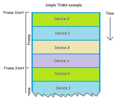
The main considerations are
that the slot sizes are kept as small as possible so that devices have the
opportunity to notify frequently, and that the slot sizes are kept large enough
so that there is no chance that a transmission from one RTU will spill into
another RTU’s air time. Also, that the Frame Start period is chosen to allow a
balance between being frequent enough to pick up new RTUs which may have gone
offline and come back, and causing excessive transmission duty cycle.
Since the MTU is responsible
for passing messages on from the user interface to the RTUs it would make sense
if the MTU had more slots per frame than each RTU, and that these slots were
interlaced amongst the RTU ones. For
example :
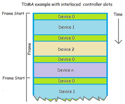
Note that the concept of the
frame does not change. The controlling device only sends a Frame Start message
at the start of the frame, not whenever it has an active slot. The Frame Start message will now have to
include details of the slot size of the controlling device as well as the slot
size shared by all the other devices, as well as the number of participants, in
order that all devices can deduce their slots from their synchronised timers.
As shown in Command Table 3
above, the Frame Start message can set notify policies for the four classes of
data (channel RAM/EEPROM application RAM/EEPROM). Setting these policies in the Frame Start message
is an implicit part of a command part of a command response, and in each slot
an RTU can respond up to four classes of data depending on the policy settings
in the Frame Start message.
Command Table 2 – Structure of Frame Start Message
|
Command |
Description |
Detail |
|
F |
Frame start message |
The start of a change on notify
frame. All RTUs should synchronise with this. The “To address” is normally
“*”. Data is as follows, all fields are
ASCII and comma delimited, the first three are 2 bytes wide, the notify
fields are 1 byte wide : <MTU TDMA slotsize in seconds (2)>, <RTU TDMA slotsize in seconds (2)>, <Number RTUs participating (2)>, <notify policy for Channel data
(1)> <number of Channel data items to return (1)> <notify policy for Channel EEPROM data (1)> <number of Channel EEPROM items to return (1)> <notify policy for Application data (1)> <number of Application data items to return (1)> <notify policy for Application EEPROM data (1)> <number of Application EEPROM items to return (1)> Notify Policy is one of :
“a” always notify
“1” notify once
“d” do not notify
“c” notify if any data changed since last time it was sent. |
Example Frame Start Message
This example sends a Frame
Start Message to all devices with the following information:
|
Frame field |
Frame value |
|
MTU slot size is |
1 second |
|
RTU slot size is |
2 seconds |
|
Maximum number of RTUs
participating is 3 |
3 |
|
send channel data in RTU
slot |
Always |
|
Number of items to send for
each channel |
1 (there is only 1) |
|
sends channel EEPROM data in
RTU slot |
Never |
|
Number of items to send for
each channel |
3 floats and 3 integers |
|
send application RAM data in
RTU slot |
Always |
|
Number of items to send |
9 floats and 9 integers |
|
send application EEPROM data
in RTU slot |
Never |
|
Number of items to send |
9 floats and 9 integers |
|
Command |
0x01 |
* |
0 |
- |
F |
0 |
x |
x |
0 |
1 |
, |
0 |
2 |
, |
|
|
0 |
3 |
, |
a |
1 |
d |
3 |
a |
9 |
d |
9 |
0x03 |
|
|
Note that “to address is” “*”
because this is a broadcast to all RTUs
Frame Start Response
Note that there is no
acknowledgement sent to a Frame Message, clearly because this is a broadcast.
However each RTU would reply,
based on the notify policy detail in the command message when its slot was
available.
The above message is asking
for channel (RAM) data and application RAM data. When their respective slots
become available each RTU responds to these as if those requests had been
individually send by command/response.
So for channel RAM the
response assumes command d with
dataset id “channel 0”
For application RAM the
response assumes command d with
dataset id “application”
For the above message we might
expect this reply from each RTU every time their slot comes around. Here we use
RTU 3 as an example.
Send channel RAM (PV values)
|
Response |
0x01 |
0 |
3 |
S |
d |
0 |
x |
x |
0 |
, |
0 |
, |
1 |
, |
|
|
0 |
, |
4 |
4 |
. |
6 |
3 |
, |
1 |
9 |
. |
8 |
2 |
, |
|
|
0 |
, |
0 |
, |
2 |
0 |
. |
6 |
3 |
0x03 |
|
|
|
|
Send application RAM (9 floats
followed by 9 integers)
|
Response |
0x01 |
0 |
3 |
S |
d |
a |
* |
9 |
0 |
. |
0 |
0 |
, |
0 |
|
|
. |
0 |
0 |
, |
4 |
. |
1 |
2 |
, |
0 |
. |
0 |
0 |
, |
|
|
8 |
. |
8 |
9 |
, |
0 |
. |
0 |
0 |
, |
0 |
. |
0 |
0 |
|
|
, |
0 |
. |
0 |
0 |
, |
0 |
. |
0 |
0 |
, |
0 |
, |
0 |
|
|
123 |
, |
3 |
, |
0 |
, |
0 |
, |
0 |
, |
0 |
, |
0 |
0x03 |
Reinitialisation
One thing not mentioned yet is
how an MTU asserts a Frame synchronisation when there are RTUs already transmitting. This could happen if the MTU reset
temporarily and had to restart the Frame.
This is achieved by getting the MTU to transmit a “silencing” Frame
Start message which tells all RTUs to stop transmitting and wait for another
Frame Start Message. In order to ensure
this is does not collide with other transmissions it is repeated a number of
times such that it is guaranteed to transmit at least once in an MTU slot.
The “silencing” Frame Start
command is of the following form
|
Frame field |
Frame value |
|
MTU slot size is |
0 seconds |
|
RTU slot size is |
0 seconds |
|
Maximum number of RTUs
participating is 3 |
0 seconds |
|
send channel data in RTU
slot |
Never |
|
Number of items to send for
each channel |
0 |
|
sends channel EEPROM data in
RTU slot |
Never |
|
Number of items to send for
each channel |
0 |
|
send application RAM data in
RTU slot |
Never |
|
Number of items to send |
0 |
|
send application EEPROM data
in RTU slot |
Never |
|
Number of items to send |
0 |
|
Command |
0x01 |
* |
0 |
- |
F |
0 |
x |
x |
0 |
0 |
, |
0 |
0 |
, |
|
|
0 |
0 |
, |
d |
0 |
d |
0 |
d |
0 |
d |
0 |
0x03 |
|
|
This is therefore what the MTU
is expected to do every time it starts up, just before it starts transmitting
its normal Frame start message.
Part
Two: An Implementation
It is my intention to add more detail and source code to this section as it becomes available.
This proof of concept implementation is intended to support four
devices on the network. The master device is implicitly device zero. In order to allow flexibility in deployment
the address of each RTU is set by jumpers, addresses 01,02 or 03 are available,
for extra addressing could be made available by using another I/O pin on the
MCU if necessary which would allow up to 7 RTUs. There is a trade off between
the update rate at the user interface and the number of RTUs as all devices are
assumed to share the same frequency via TDMA.
Radio Hardware
|
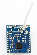
These XRF units from Ciseco were chosen for the radio link. They are very easy to use and connect
directly to a serial interface. After
writing the initial serial comms code I literally removed the serial cable
linking the MTU and an RTU and plugged in the XRFs and they just carried on
working as if there was a cable in place. No configuration to do - they just
work. These devices are theoretically
capable of over 1000m although I have not got much beyond 200m in my own
tests – but this is more than adequate for this project. Note that because they connect to the
serial interface they are easy to upgrade.
For example the ARF unit is expected to be capable of 10’s of Km and connect via a serial
interface. A little over the top for
what I envisage though. The default frequency of 868.3Mhz and speed
of 9600 baud were used, though these are both configurable on these radio
units. |
|
MTU
Hardware
|
For the MTU I wanted
something which could run a web server and application and have a small
footprint and so the Raspberry Pi was an obvious contender for this. The picture shows one fitted
with XRF card (mounted on a Ciseco Slice of Pi breakout board), and an Edimax
EW-7811UN USB 802.11 WiFi adapter. |
|
Software
The OS used on the Raspberry
Pi was the 2013-02-09-wheezy from
I used nginx for the web
browser which was straightforward to download, install and configure.
I hope to expand the details
of the configuration here at a later date.
I needed to develop four
modules of software for use on the MTU
|
scampmtu |
This program (written in C)
is the essentially the MTU itself and chats over the scamp interface to the
RTUs. Its main tasks are : ·
To
control the TDMA framework and broadcast Frame start messages to the RTUs at
the beginning of each frame. ·
To
receive data back from the RTUs within their respective TDMA slots, and store
the data for reading and displaying by the web page. ·
To
detect commands from the web page and send then on to the appropriate RTU in
the next available MTU TDMA frame slot. To do all this the following
files are used : /usr/share/nginx/www/SCAMP/data/fsp.txt This file holds the configured
frame start parameters as configured from the Web user interface. This is read on each frame by the MTU so
that new changes are detected and sent in the next Frame Start command. /tmp/rtunotifydata.txt The MTU stores any messages
received by the RTUs in this file so they can be read and presented by the
web user interface. The file is
deleted at the end of each frame by the MTU /tmp/requestconfig.txt When the user interface
wishes to read EEPROM data it creates this file with “1” in it. When the MTU detects this it immediately
restarts the frame on its next slot with the two new EEPROM notify policies added
temporarily into the next Frame start command, requesting that the two EEPROM
message types are sent once. The MTU then deletes the file. Each RTU will then, in its next available
slot respond with the EEPROM data in addition to the regular data it is
configured to return. The Frame Start
command is then reset to its original state.
This is useful to use when the browser is refreshed – this allows the
latest EEPROM to be sent to the web page. /tmp/pendingcommand.txt If the user wishes to change
the value of an output channel (e.g.
change a PWM value or a digital output) the web page stores the SCAMP command
in this file which is detected and transmitted to the addressed RTU on the
MTUs next frame. The file is then
deleted. In the initial implementation
only one command can currently be queued at a time. |
|
scamp.php |
This is the web user interface, and in the end did not make much use of PHP. AJAX is used to to allow the web page to interface with the main MTU code via the files described above files. In addition it uses google line chart to provide some PV/PID graphing capability. |
|
rtuchat |
Written in C, this is a
utility which was written to exercise and debug the scamp commands and was
used to demonstrate the example dialogues earlier in this document. It allows a command to be typed in and sent
to an RTU and then displays the response to the console window. |
|
rtuconfig |
Written in C, this program
simply reads an input file of write commands which set initial eeprom
settings in each RTU. This is much easier than having to set them all from
the user interface. Commands are stored in an
input file www/SCAMP/data/rtuconfig.txt |
MTU TDMA
|
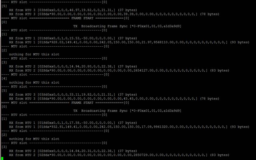
This screenshot of scampmtu running, shows the structure of the TDMA
frame. It is configured for 1 second
RTU slots interlaced with 1 second MTU slots for three RTUs. The image shows the RTU issuing a Frame
start message, followed by replies from all three RTUs, returning channel data
(for all 9 channels) and application data
(9 floats followed by 0 integers) within their allocated slots. |
RTU
Hardware
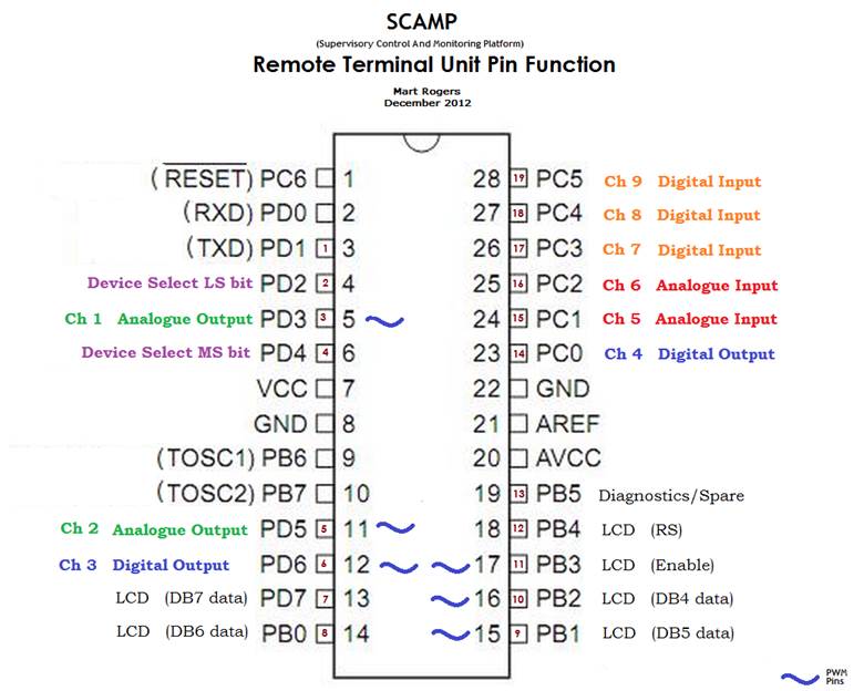
SCAMP RTU Pin Function
The RTUs were implemented using an AVR ATMega328. The pin allocation to Channels, Address jumpers and LCD is shown below. There is no reason why an Arduino or Arduino clone board could not be used.
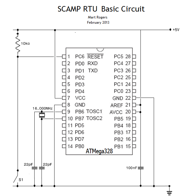
Basic RTU Circuit
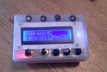
|
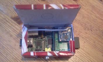
This implementation of an RTU has all nine channels connected up to LEDs, an LDR, Temperature sensors (analogue and digital) and input switches. There are a number of pages of display which can be stepped through using one of the switches, showing live IO and PID values as well as comms messages being received and sent. The volume of the package could be greatly reduced, but this prototype had to hold all nine sensors and wiring, an LCD and a PP3 battery as well as the XRF and the MCU circuit board. |
|
|
|
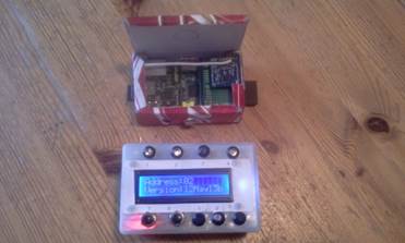
|
A side by side comparison of an MTU and
an RTU |
Software
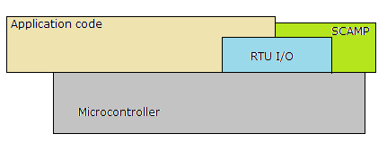
RTU Software Architecture.
The layering of the RTU software is such that the application code and SCAMP code must access mapped memory via a common layer so that changes made by one can be realised by the other. This is referred to as the RTU IO layer. The application code can access the MCU directly for anything else, and the SCAMP layer is shown as accessing the MCU directly only in order to carry out serial communications over the MCU’s UART.
RTU IO API
The RTU IO API provides the following functions to allow the application code and the SCAMP layer access to Channel data and EEPROM and application RAM and EEPROM
|
Events |
|
|
void Event_RTUIO_DIChange(unsigned char channel, int state) |
To be implemented by the application. This event fires whenever a digital input changes. |
|
Channel Data Access |
|
|
int RTUIO_writechannel
(unsigned char channel, unsigned int intval) |
Writes data to a digital output or an analogue output. |
|
unsigned int RTUIO_readchannel(unsigned char channel) |
Reads the raw value on any channel (input or output) |
|
int RTUIO_readchannel_eu (unsigned char channel, float *floatval, unsigned int * intval) |
Reads the engineering units value on any channel. If 0 is returned value is a float, otherwise an integer. |
|
Application Data Access |
|
|
void RTUIO_writevar_word (int index, unsigned int val) |
Writes an integer to application RAM at the selected index |
|
void RTUIO_writevar_float (int index,float val) |
Writes an float to application RAM at the selected index |
|
unsigned int RTUIO_readvar_word (int index) |
Reads an integer from application RAM at the selected index |
|
float RTUIO_readvar_float (int index) |
Reads a float from application RAM at the selected index |
|
EEPROM Data Access |
|
|
void RTUIO_writeconfig_word (unsigned char datasetID, unsigned char dataindex, unsigned int data) |
Writes an EEPPROM integer to Channel or Application at the selected index. |
|
void RTUIO_writeconfig_float(unsigned char datasetID, unsigned char dataindex, float data) |
Writes an EEPPROM float to Channel or Application at the selected index. |
|
unsigned int RTUIO_readconfig_word(unsigned char datasetID, unsigned char dataindex) |
Reads an EEPPROM integer from Channel or Application at the selected index. |
|
float RTUIO_readconfig_float (unsigned char datasetID, unsigned char dataindex) |
Reads an EEPPROM float from Channel or Application at the selected index. |
|
char * RTUIO_readdataset_group(unsigned char cmd, unsigned char datasetID, unsigned char numelements, char * data) |
Reads a comma delimited list of values from a Channel or Application. numelements floats are followed by numelements integers. |
|
General |
|
|
void RTUIO_init() |
Initialise RTU IO layer |
|
void RTUIO_service() |
Schedules RTUIO layer housekeeping. Must be called from foreground loop |
|
void RTUIO_1000Tick() |
Schedules RTUIO layer housekeeping. Must be called every 1s. Used for doing things like rereading Dallas sensors every so many seconds. |
|
int RTUIO_getnumchannels() |
Returns the number of channels supported by the MCU |
|
Utility functions |
|
|
char *
RTUIO_FloatToString(float floatval, char * answer, int fTagComma, int fConCat) |
Converts a float to a string with options to add a comma and to concat result into answer rather than copy. |
|
char *
RTUIO_WordToString (unsigned int intval, char * answer, int fTagComma, int fConCat) |
Converts an integer to a string with options to add a comma and to concat result into answer rather than copy. |
Libraries
This implementation
added libraries for HD44780
LCD interfacing and single drop DS8B20 Dallas temperature sensor.
LCD Wiring
The ATMega328 used in this implementation provides sufficient I/O that a HD44780 LCD (which in 4 bit mode requires six I/O pins) The pin out and wiring is shown below.
|
LCD Pin |
Symbol |
Function |
Wiring Details |
AVR Pin/Symbol |
|
1 |
Vss |
0v |
To 0v rail |
|
|
2 |
Vdd |
+5v |
To 5v rail |
|
|
3 |
Vo |
Contrast |
To 0v rail via 10K VR |
|
|
4 |
RS |
Register Select |
To AVR |
Pin 12/PB4 |
|
5 |
R/W |
Read/Write |
To 0v rail |
|
|
6 |
E |
Enable |
To AVR |
Pin 11/PB3 |
|
11 |
DB4 |
DB4 data |
To AVR |
Pin 10/PB2 |
|
12 |
DB5 |
DB5 data |
To AVR |
Pin 9/PB1 |
|
13 |
DB6 |
DB6 data |
To AVR |
Pin 8/PB0 |
|
14 |
DB7 |
DB7 data |
To AVR |
Pin 7/PD7 |
|
15 |
A |
LED anode |
To 5v rail via 180R |
|
|
16 |
K |
LED cathode |
To 0v rail |
|
The library is compiled for up to 4x20 display layouts though only 2x16 have been tried.
Dallas wiring
With the chosen library (see above) only single drop (one device per digital input) is supported in this initial implementation. Wiring is in non-parasite mode (ground pin to 0v, VDD to 5v, and DQ to channel 7,8 or 9). No resistor is necessary for short runs of less than 1 metre.
See http://datasheets.maximintegrated.com/en/ds/DS18B20.pdf
Part
Three: A SCAMP PID Application
Objective
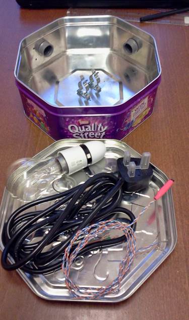
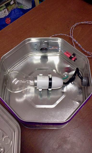
The objective here was to see how SCAMP could be used to monitor and control a simple PID Control Loop. Temperature control was an obvious choice and was an inexpensive and quick choice to manufacture a rig for. A metal Quality Street container, a 100W light bulb with socket and a Dallas DS18B20 were assembled as shown in the pictures below:
|
|
|
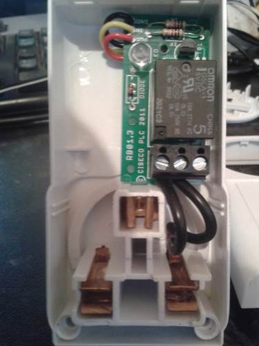
Driving the Control Variable
In order to switch the mains voltage from the RTU a Ciseco 5v, 10A relay board was used :
http://shop.ciseco.co.uk/kit-relay-board-simple-to-use-5v-operation-supports-logic-level-also-10amp/
This was fitted into the case of a Maplin remote control socket which had had its internals removed.
|
|
|
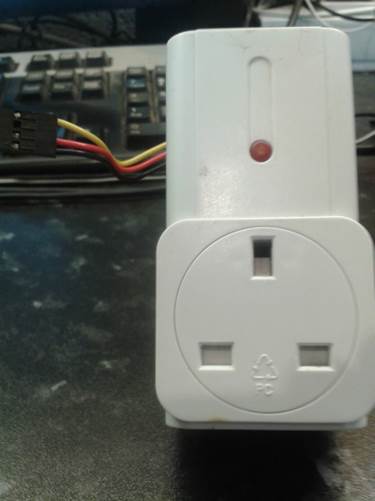
The light bulb cable was then plugged in to this socket, the DC side of the socket was connected to one of the RTU digital output channels (channel 3) and to the 5v supply on the RTU. The light bulb could now be turned on or off, by toggling the RTU channel 3 value.
Monitoring the Process Variable
In order for the RTU to realise and monitor the temperature, all that
was required was to connect the Dallas probe back to one of the digital input
channels (channel 9) and the 5v RTU supply, and then to configure the
Engineering Units to DS18B20 sensor °C
by setting the appropriate value in Channel EEPROM Integer 0 (see Page 7).
Assigning
Mapped Memory
As described in
part one, areas of RAM and EEPROM are accessible by both the RTU/MCU and the
SCAMP interface. In order to use these
in any SCAMP application requires that we define the data we wish to share and
allocate it to the mapped data.
This is the
allocation for the PID application:
|
Configuration data item |
Memory Location Used |
|
Setpoint |
Application EEPROM float 0 |
|
Proportional Gain |
Application EEPROM float 1 |
|
Integral Gain |
Application EEPROM float 2 |
|
Derivative Gain |
Application EEPROM float 3 |
|
|
|
|
Control Type (None/P/PI/PID) |
Application EEPROM integer 0 |
|
Cycle Time |
Application EEPROM integer 1 |
|
Frame Time |
Application EEPROM integer 2 |
|
Proportional Band |
Application EEPROM integer 3 |
|
PV Channel |
Application EEPROM integer 4 |
|
CV Channel |
Application EEPROM integer 5 |
|
Live data item |
Memory Location Used |
|
Error (Setpoint-PV) |
Application RAM float 0 |
|
Proportional Term |
Application RAM float 1 |
|
Integral Term |
Application RAM float 2 |
|
Derivative Term |
Application RAM float 3 |
|
Sigma Term (Aggregated
Error) |
Application RAM float 4 |
|
Next CV (most recently
calculated CV value) |
Application RAM float 5 |
|
Current CV (CV value in
current |
Application RAM float 6 |
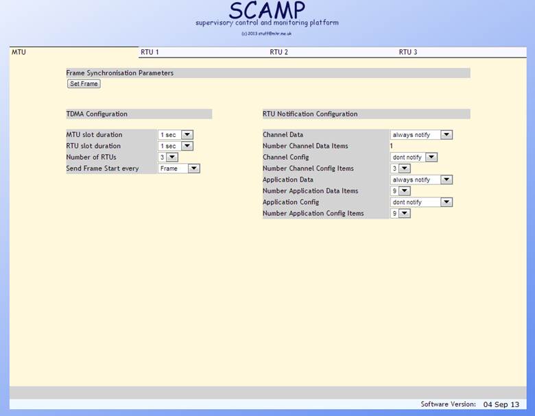
User
Interface
The user interface
is a web application running on the MTU.
It is implemented in HTML and javascript/AJAX, and has a tab for each
RTU and one for configuring the MTU Frame settings. The web page interface with
the MTU via the interface files described in the MTU software section in Part
Two of this document. This allows data
sent to the MTU to be displayed, and allows the user interface to send command
to chosen RTUs via the MTU.
For this
application we are using just RTU 2 and its tab for configuration and
monitoring is shown below
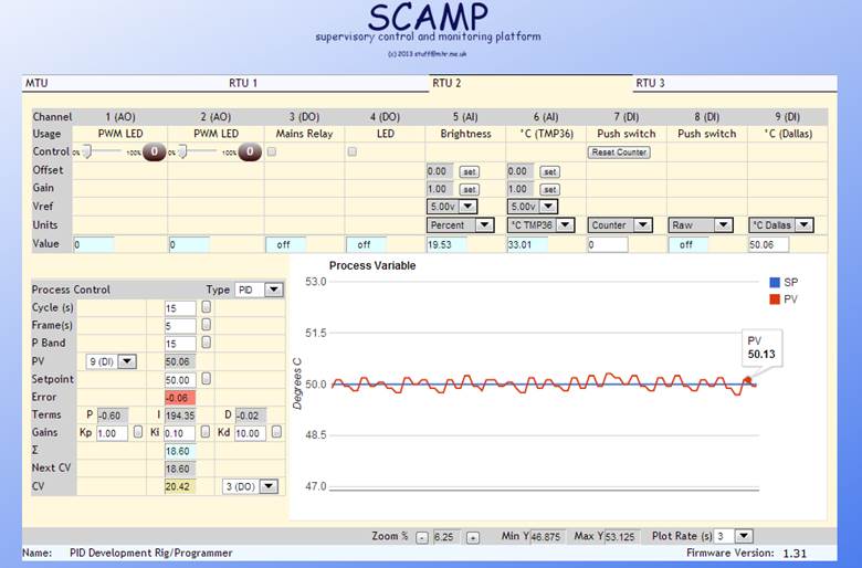
The horizontal
section above the graph shows the nine channels, and their engineering units as
configured in reserved EEPROM. In
addition channels 5 and 6 which are analogue in have have EEPROM for Offset,
Gain and ADC VRef.
This application
only uses two channels one is the Process Variable (channel 9 a digital input ,
measuring degrees C, with its engineering units set to °C Dallas) and the Control
Variable (channel 3 which is a digital output driving a relay).
The panel to the
left of the graph shows the configuration data and live data for the PID
application, these items are the ones allocated to SCAMP shared memory, in the
table on the page before last. The graph on the right of the panel tracks the
PV in real time. The plot rate and scale can also be changed on the fly from
the controls below the graph.
The PV and CV drop
down controls in the panel on the left of the graph allow any input channel and
any output channel (respectively) to be connected to the PID software on the
fly.
Although the tuning
parameters (Kp,Ki,Kd) have only been set roughly so far, they are all
changeable from the user interface, as are all the EERPROM values.
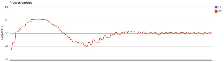
This trace of PV
shows a 10 minute snapshot starting shortly after running up from ambient temperature
(~20 degrees C). After about 6 or 7 minutes even with untuned PID parameters,
the PV is holding at the setpoint of 50 degrees C with a variance better than
±0.3 degrees.
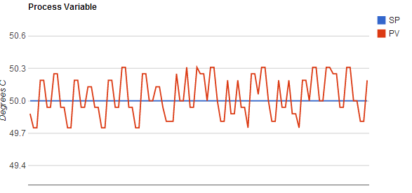
PV trace with scale
zoomed to show variance.
Choosing PID Data Settings
The data settings
for this application were derived as follows :
Terminology
|
Process Variable PV |
the measured process output, in this case the current temperature of the tin. |
|
Error |
The difference between the Setpoint and the current PV |
|
Control Variable CV |
A value required to zero out the Error. In this case a value which will drive the heater in the tin. |
|
Frame Time |
Fundamental computational period for Error and CV. |
|
Cycle Time |
The period chosen to output PWM power to drive the heater |
|
Cycle Resolution |
The timespan that the Cycle Time is divided into |
|
PV Total Range |
This is the full range that it is expected that we could be controlling the PV over |
Expected Setpoint
|
Setpoint |
50.00
degrees |
Cycle Time
This is calculated empirically by heating the tin from ambient starting point to set point of 50.00 degrees, then intersecting 63% of that time. The Frame Time needs to be approximately 10 times faster than that value.
|
Starting
temperature |
16.7
degrees |
|
Time to
50.00 degrees |
4:40s |
|
63% of
time to setpoint |
63 * 280
/100 = 176.4s |
|
Cycle Time |
15s |
|
Cycle Resolution
|
100ms |
Frame Time
This has been set so that it takes place more than once during a Cycle
But this is somewhat arbitrary
|
Cycle Time |
5s |
PV Total Range
Chosen to be :
|
PV Total
Range |
0 to 100
degrees C |
Proportional Band
This is set at 15% of the PV Total Range and is therefore
|
+ve Proportional Band |
35.00 degrees to Setpoint |
|
-ve Proportional Band |
Setpoint to 65 degrees |
As this system is only driving in one direction and is relying on ambient temperature for cooling the –ve Proportional Band will not be implemented. This means that CV will be applied as follows
|
|
CV |
|
Below +ve Proportional band |
100% |
|
Within +ve Proportional band |
Proportional to error |
|
Within -ve Proportional band |
Proportional to error |
|
Above -ve Proportional band |
-100% |
Note that since we are relying on ambient temperature to cool, the CV used within and above the –ve Proportional Band may be implemented as 0 CV.
Calculating the relationship between Error and CV
The +ve proportional band is 15 degrees
Number of degrees Celcius of Error for each Cycle Resolution =
Proportional Band/Number Frame Resolutions
= 15 degrees / 15s @100ms
= 15 /150 =0.1 degrees
Error = CV * 0.1
Therefore CV is derived from error by
|
CV = Error * 10. |
This is verified by checking that 100% error consumes a full Cycle Period
CV = 100% of proportional band * 10
CV = 15 * 10 = 150 Cycle resolutions
CV = 150 * 100ms
CV = 15000ms = 15s
100% error consumes a full Cycle Period
Disclaimer
Warning: This
project is a prototype, for fun and proof of concept, all documentation and
code made available are provided in the hope that they will be useful, but
without any warranty; without even the implied warranty of merchantability or
fitness for a particular purpose. All source code is made available under GNU
General Public License.
Copyright © MHR
2013